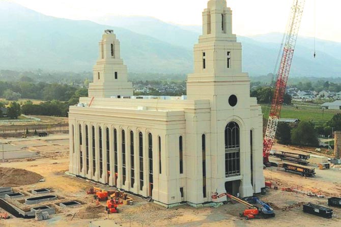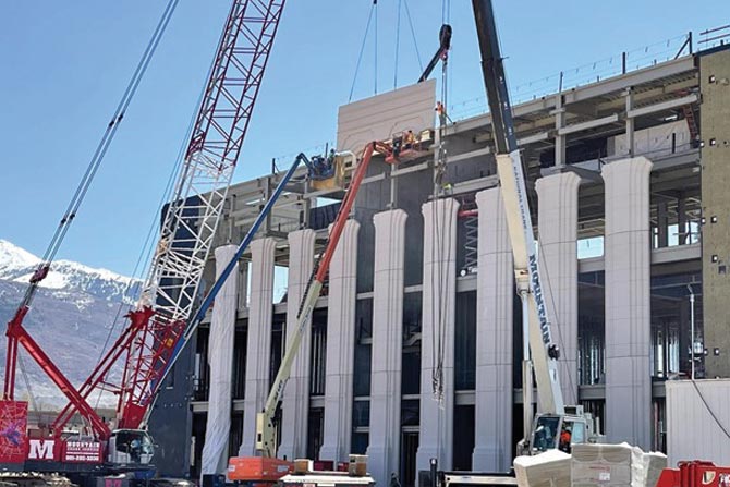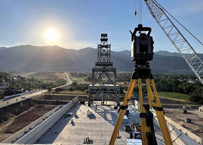


Construction of the Layton temple began summer of 2020. Diamond Land Surveying joined the project after the footings and the lower part of the sheer walls were already poured. Diamond was contracted to mark out over 400 precast concrete panels encapsulating the structure. The top left photo on the following page shows the view from the east tower of the temple at approximately 125 feet above the main floor.
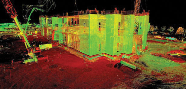
The structure’s design was orientated east-west, framed with steel, and included massive sheer walls at each end. Each precast panel was required to be spaced 3/4” from the surrounding panels on all sides. Outwest Construction installed the panels and prescribed an 1/8” tolerance for the layout marks. To ensure the precast panels would fit correctly to the building, an as-built scan of the footings, sheer wall, and steel framing was performed. The scan data revealed that the structure’s length was built slightly shorter than the design. To compensate for this, new baselines were designed so the panels would fit on what was actually constructed. These new baselines were set and marked with chalk around the footings and roof of the temple. All dimensions were pulled from these baselines.
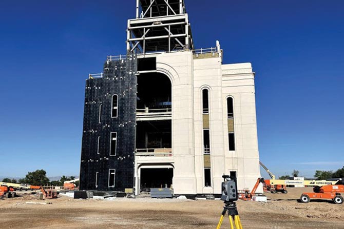
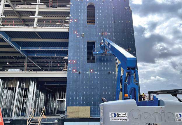
The next step was to mark out the locations of hundreds of steel mounting plates pre-welded onto the structure to hold the panels in place. These pre-welds were marked on the steel framing and steel plates embedded into the sheer walls. Dozens of the embeds had to be marked and dug out of the water-proofing and insulation. Several had to be moved and re-anchored to the sheer walls due to as-built conditions. The layout crew had to adapt based on site conditions and other trades working on the temple.
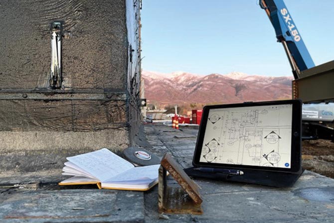
After the pre-welds were installed, stickers were placed around the structure that showed the exact corners and orientation of every panel. These 6” square stickers were permanent and blank. Before each day’s layout, the stickers needed were drawn on with a square and compass and then labeled. Once placed, they controlled the height and position of each panel. A combination of steel tape, laser and total station equipment was used to place the stickers and pre-weld locations precisely and accurately.
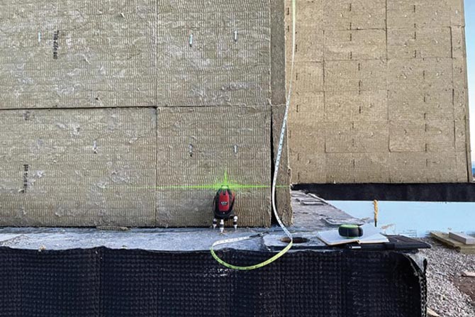
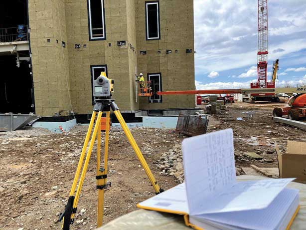
Most of the layout was done by setting a laser at a precise spot on the baseline, then pulling a tape up the building to mark the panels. The total station was then used to check the placement of the layout. A lot of the layout was done at night to better see the laser and avoid other trades on site.
The process of marking the locations of the panels involved at least two people. One person was on the ground (or roof when working on the towers) below the other person to move the laser, hold the tape, call out dimensions via radio, and then check the marks with a total station. The other person was in a lift or perched on the steel to mark the panels or place the stickers.
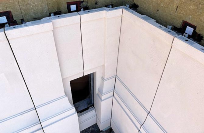
The 3/4” gap between the panels was eventually grouted and finished. Staying within the small tolerances for the layout was crucial to the construction. These panels were fabricated in California and then shipped to the job site. Most of the panels were so large that only one could be shipped at a time, and they had to be installed within a day or two of shipment because there wasn’t room on site to store the panels. Each panel had to fit the first time, and there was no room in the design to compensate for any errors in the survey. Each mark was checked and then checked again. Also, the pre-cast panels were designed to precisely fit over the many windows of the structure. Prefabricated glass panels were installed in these windows. The pre-cast panels and the glass could not be easily or significantly modified on-site. They simply had to fit when they were installed.
One of the major challenges to this project was finding a balance between the building’s design and how it was actually constructed. Meeting this challenge involved comparing the terrestrial LiDAR (Light Detection and Ranging) data with the construction plans and then adjusting the plans to mark out where the panels could be placed without any gaps or overlaps in the finished product.
Another problem was finding a way to safely mark out the panels/pre-welds in hard-to-reach places. This was done by a combination of personnel lifts and climbing the steel with fall protection in place. Every tool in a surveyor’s arsenal was used, from a lowly plumb bob and string to the most sophisticated total stations and LiDAR scanners. All of this happened while workers were dozens of feet above the ground.
Everyone at Diamond Land Surveying grew as surveyors during this project. The layout lasted about nine months, and there were as many as seven surveyors from Diamond at the site on any given day. Coordination between the trades was crucial to getting the layout done in a safe and timely manner. Almost daily meetings were held between the survey crew and other trades such as the installers, waterproofers, insulators, crane operators, steelworkers, electricians, delivery trucks, etc. Each day saw new challenges, such as a change in the construction plans or how one area was prepped, but the installers needed layout in a different area. Because of this, the layout crew’s plans for the day were constantly evolving. Meeting with the other trades at their day’s end, and then performing the layout into the night helped the crew avoid surprises and gave them the ability to move the personnel lifts and other equipment without interference. Most of the layout was calculated on-site, so an up-to-date knowledge of the plans, and access to the engineers who designed the panels, was vital. The techniques learned, and the tools used will serve these surveyors for the rest of their careers.
AMOS WILSON, PLS
Amos has been surveying in Utah for over six years and has experience in LiDAR, Drones, Construction and Boundaries. He now owns and operates Aegis Land Surveying.